
 EN
EN
Large compressor systems demand precision engineering in every component, and the lip seal plays a critical role in maintaining operational integrity and efficiency. A lip seal functions as a dynamic barrier between the rotating shaft and the stationary housing, preventing compressed air and lubricants from escaping while blocking external contaminants from entering the system. Understanding how a lip seal performs under extreme pressure, temperature, and speed conditions is essential for operators, maintenance teams, and equipment designers who need to minimize downtime and extend service intervals.
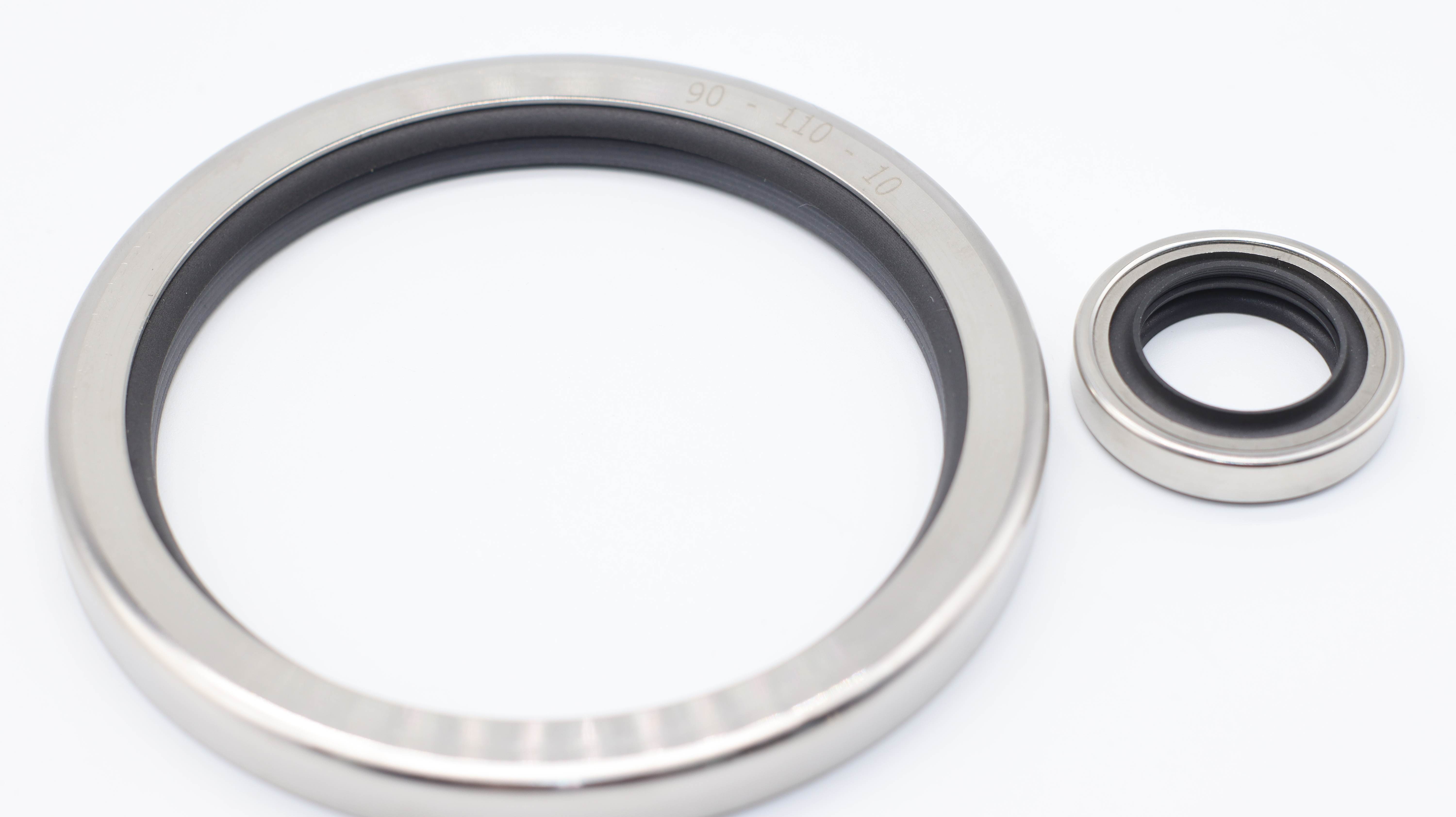
In large compressor systems, selecting the right lip seal material and design directly influences leakage rates, wear progression, and total cost of ownership. PTFE-based lip seal designs have emerged as industry standards because they offer superior chemical resistance, low friction characteristics, and thermal stability across the demanding operating ranges typical of modern compression equipment. This article explores the mechanisms behind leakage and wear in lip seal applications, providing practical analysis frameworks that help maintenance professionals and engineers optimize seal performance and predict replacement intervals with greater accuracy.
How Lip Seal Leakage Develops in Compressor Applications
Pressure-Induced Leakage Pathways
Leakage through a lip seal occurs when pressurized fluid finds microscopic pathways around the sealing edge. In large compressor systems, the differential pressure across the lip seal can reach several bar, creating a continuous hydraulic force that tries to push fluid past the seal interface. The lip seal is designed with an interference fit that presses against the shaft surface, but this interference decreases over time as the elastomer material creeps or the lip edge becomes rounded. When the contact pressure falls below a critical threshold, leakage rates increase exponentially, even if the lip seal appears visually intact. Understanding this pressure-leakage relationship helps maintenance teams recognize early warning signs before catastrophic seal failure occurs.
Surface Finish and Shaft Runout Effects
The microscopic surface finish of the rotating shaft directly determines how effectively a lip seal can maintain contact. If the shaft surface has scratches, corrosion, or microburst defects, the lip seal cannot establish a continuous barrier, and leakage paths form immediately. In large compressor systems, the shaft often rotates at speeds between 3,000 and 15,000 rpm, and any radial runout (shaft wobble) causes the lip seal to cycle between full contact and partial lift-off with each revolution. This cyclical motion accelerates wear and disrupts the hydrodynamic film that helps distribute lubricant between the lip seal and shaft. Regular shaft inspection and runout measurement are therefore critical preventive maintenance steps that directly reduce leakage rates and extend lip seal service life.
Wear Mechanisms Affecting Lip Seal Durability
Abrasive Wear and Particle Contamination
Abrasive particles within the compressed air or lubricant are the primary drivers of accelerated lip seal wear in large compressor systems. When a hard particle becomes trapped between the lip seal edge and the shaft surface, it acts as a grinding tool that scores the lip seal material with each rotation. The lip seal, which was previously maintaining a smooth contact face, now has microscopic grooves that reduce sealing effectiveness and increase leakage. In industrial environments, even supposedly clean compressed air contains metallic dust, condensate contaminants, and degradation byproducts that accumulate over months of operation. Installing high-efficiency filtration upstream of the compressor and regularly replacing air intake filters significantly reduces the particle load that reaches the lip seal, directly improving durability and reducing unplanned maintenance events.
Thermal Degradation and Chemical Attack
Temperature extremes are another critical wear driver for lip seals in large compressor systems. Compressor discharge air can reach 90°C or higher under full load, and sustained exposure to this heat causes the elastomer in a standard lip seal to lose elasticity and become brittle. PTFE-based lip seal designs tolerate higher temperatures better than traditional nitrile or fluoroelastomer lip seals, but they are not immune to thermal degradation. When a lip seal operates near its temperature limit for extended periods, the material becomes less flexible, the interference fit decreases, and leakage increases. Additionally, certain lubricants or residual chemicals in the compressed air stream can chemically attack the lip seal material, accelerating molecular breakdown. Monitoring discharge temperature and ensuring proper lubricant selection for the operating temperature range helps prevent premature lip seal failure caused by thermal or chemical stress.
Practical Wear Analysis and Performance Monitoring
Visual Inspection Protocols for Lip Seal Condition Assessment
A systematic visual inspection routine provides the first line of defense for detecting lip seal degradation before catastrophic failure. Maintenance teams should examine the external surface of the lip seal housing for visible oil or air leakage, which directly indicates that the lip seal is no longer maintaining pressure. If leakage is present, the lip seal should be scheduled for replacement during the next planned maintenance window. A slightly moist surface is often acceptable, but steady dripping signals that the lip seal interference has dropped below acceptable levels. Additionally, checking for discoloration or hardening of the external rubber or plastic surfaces can indicate thermal stress or chemical exposure that has compromised the lip seal. In large compressor systems where environmental conditions are harsh, a documented visual inspection schedule—typically monthly for critical units and quarterly for standard operations—provides early warning signals that help planners allocate resources before failures cascade.
Measuring Leakage Rates and Setting Replacement Thresholds
Quantifying actual leakage rates from a lip seal allows maintenance teams to track wear progression and predict end-of-life timing with greater precision. Several methods exist to measure leakage from a lip seal in a large compressor system: collecting dripped oil in a calibrated container over a fixed time period, using smoke or gas tracer methods to visualize air leakage paths, or comparing system pressure stability before and after suspected seal degradation. Once baseline leakage measurements are established for a given lip seal installation, maintenance personnel can monitor whether leakage is stable, slowly increasing, or accelerating. Leakage that doubles over a month indicates wear is accelerating and the lip seal should be replaced within weeks rather than months. Establishing clear leakage thresholds—for example, replacing a lip seal if leakage exceeds 10 ml per hour—eliminates guesswork and ensures preventive replacement schedules align with actual seal condition rather than arbitrary calendar intervals.
FAQ
What factors influence how quickly a lip seal wears in a compressor system?
Lip seal wear rates are driven by multiple interconnected factors: operating temperature, differential pressure across the seal, shaft surface finish and runout, contamination levels in the compressed air and lubricant, rotational speed, and the chemical compatibility between the lip seal material and the operating fluid. Systems operating at higher temperatures with higher pressure differentials and faster shaft speeds experience faster wear. Contaminated systems with poor air filtration experience accelerated abrasive wear of the lip seal, while proper maintenance of shaft geometry and surface finish extends lip seal life significantly. Understanding which factors most heavily influence wear in a specific installation helps prioritize maintenance interventions and design upgrades.
How can leakage from a lip seal be distinguished from other sources of compressor fluid loss?
Leakage from a lip seal typically appears as a continuous wet spot around the shaft area, with oil or liquid accumulation increasing steadily over days or weeks. In contrast, leakage from a cracked housing or corroded connection appears more suddenly and often in larger volumes. Air leakage from a lip seal presents as a faint hissing sound at the seal interface and can be detected with soap spray solutions that form bubbles at the leak source. Pressure testing—measuring system pressure stability while the compressor is offline—helps confirm whether a lip seal is the actual leak source or whether the pressure drop is coming from downstream process components. Experienced maintenance personnel develop a tactile and auditory sense for identifying lip seal leakage through careful observation during routine inspections.
Should a lip seal always be replaced when visible leakage appears?
Not necessarily. Very minor leakage—a few droplets per day from a lip seal operating in a large compressor system—may be acceptable in some applications where downtime costs for replacement exceed the cost of controlled leakage. However, leakage that is increasing in volume, leakage that saturates surrounding components with oil, or leakage that indicates the lip seal has lost effective sealing function should trigger replacement. Many industrial standards recommend replacing a lip seal before visible leakage becomes apparent, using predictive maintenance data such as wear rate trends and thermal monitoring. The decision to replace or monitor further should balance the cost of replacement labor and parts against the operational risk and business impact of continued operation with a degraded lip seal.